Table of Contents
- Introduction and Disassembly
- The best way of Disassembly (Feb 08 2007)
- Using the module in your own circuits
- Analog front end of control board (Feb 09 2007)
- Another way of using the gun
- Great, so how do we change the frequency?
- The Trouble with Chirples
- Spectral Output (Feb 06 2007)
- Repurposing the LCD (Feb 10 2007)
Hacking the Hot Wheels Radar Gun
The Hot Wheels Radar Gun is a real radar gun currently (Feb 2007) available from Walmart and other retailers for about $30 (USD). It is a real radar gun, operating at 10.525 GHz capable of clocking cars, people, pets, and toys.
Here and here are sites that discuss the product. The Austech site goes into great depth on how the device works.
But before you can play with it, you've got to get the thing open! Here are some pictures of me taking the thing apart. There are about a dozen screws that are covered with plastic that need to be removed. You will first have to drill out the plastic to get to these screws if you want to completely disassemble the gun. Note: There is a better way of doing this here if all you want to do is gain access to the signal wires.
WARNING! Clicking on the thumbnails will bring you to a large photo, which while under a megabyte each, might clog your internet tube.
 | The radar gun |
 | The gun, with some of the holes drilled out and the front and rear rings removed |
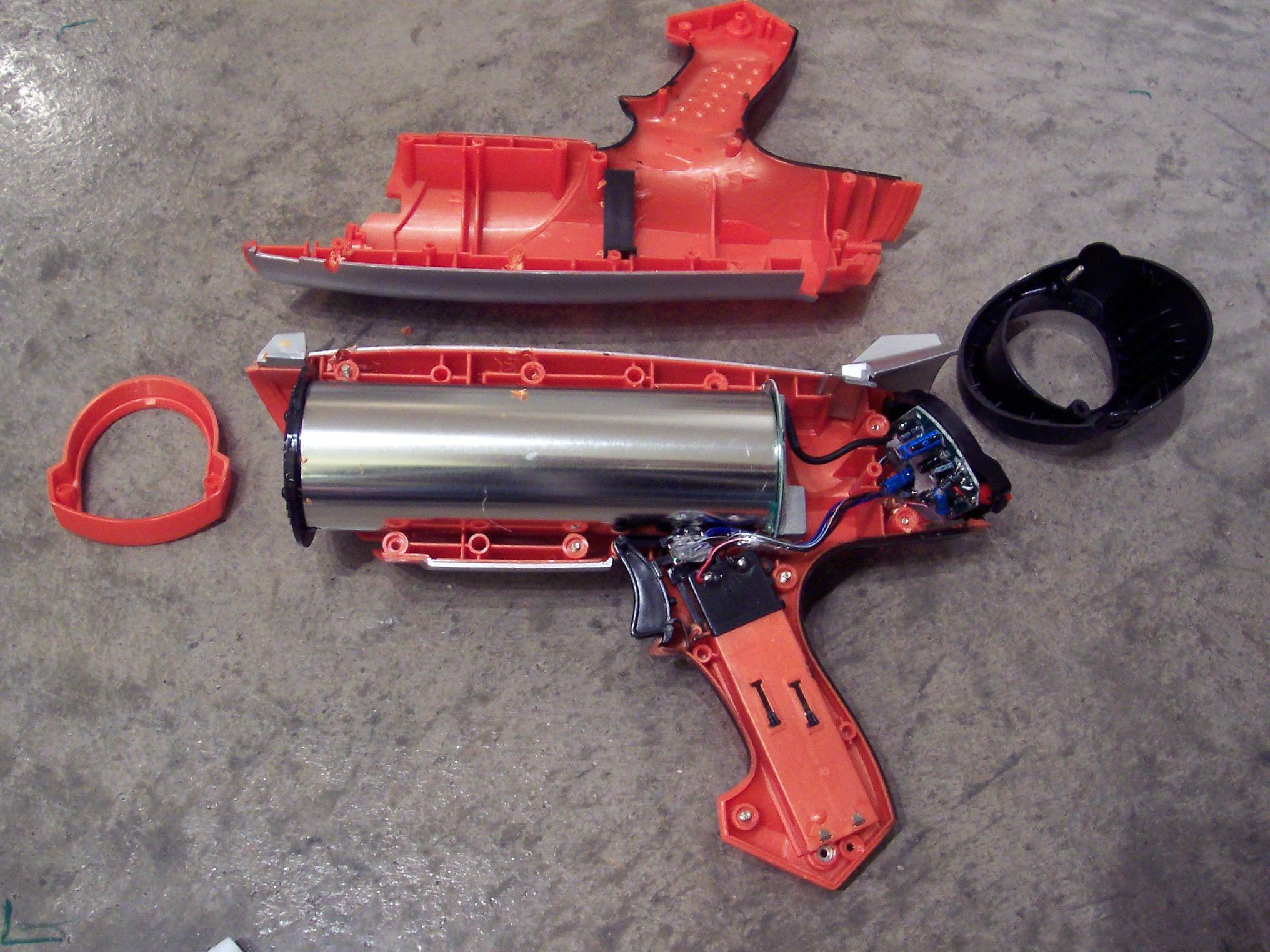 | Taken apart, showing both halves of the casing, the waveguide, the control board, and the switch |
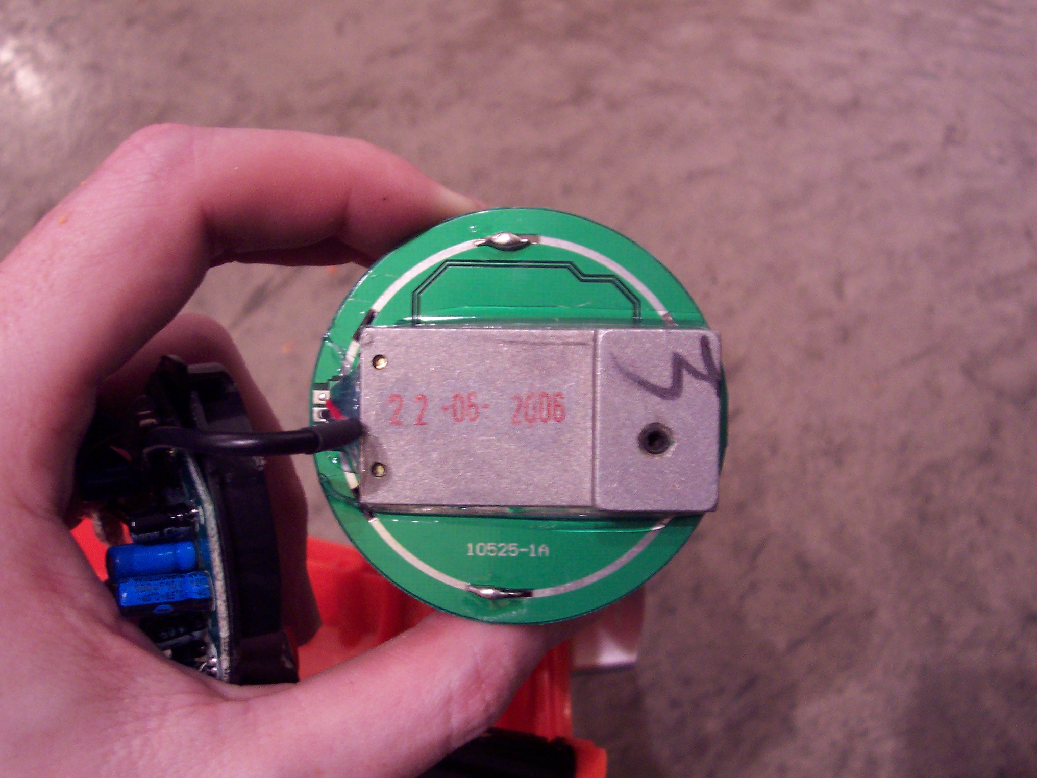
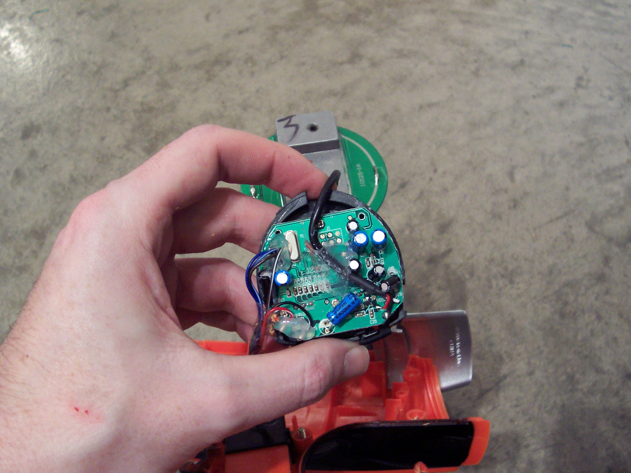 | The back of the control board/screen module |
 | The business end of the waveguide |
 | The switch and battery assembly |
 | All the guts strung out |
 | Looking down the waveguide; you can see the TX and RX antennas (the four little green squares) |
 | Another view down the waveguide |
Once you have it open, you can play with the TX/RX module. It has three wires coming out of it: black, red, and white. Black is ground and red is Vcc, at 4.5 volts. It seems to run okay off anything near 4.5 volts; I simply use a 5 volt regulator and a diode to drop 0.6 volts before for supplying the module.
The module constantly transmits 10.525GHz when supplied power. The module then receives the reflected signal and mixes it with the transmit oscillator. The result is a sinusoid with a frequency equal to the diffrence in frequency of the transmitted and received signal. (Also the sum of the two frequencies is present, but the 21.050 GHz signal is filtered or otherwise lost in the module.)
If the tranmitted signal is bounced off something that is moving, then you can find the speed of the object by measuring the frequency of the output. Thats how the radar gun works in the first place. Read up on "Doppler Radar" to learn more.
The easiest way to disassemble the gun
After purchasing my second radar gun, I realized that you could gain access to the waveguide signals very easily! You don't need to drill out all the screws covers and pry everything apart.
All you need to do is drill out or pop off the covers to the screws on the displace face plate. These are very easy to get out. With a little bit of prying and bending, you can pop the black plastic piece that the LCD is mounted to. You will then find the control board and wires free for use. Just unsolder the wires and you're good to go!
There are three wires to the wave guide, bundled together. There are four wires from the trigger switch, one set a normally-open switch and the other pair normally closed switch. Finally, there are the two wires from the battery pack in the handle. You even have some space to fit a small PCB of your own design back into the gun, for a slick hack.
 | The end of the gun removed |
 | A detail of the wires with voltage dropping diodes soldered |
 | A detail of a single tranistor amplifier board |
 | A hack well done |
Using the module in your own circuits
There is interest in making a radar unit useful to robots, mainly for detecting objects at distance. The raw signal out of the module is sort of weak, however.
Here is my current breadboard circuit:
[Radar Module]------------[Amplifier]-----------[Comparator]----------------o
              (less than             (less than             (5v squarewave)
                20mVpp)                2 Vpp )
The amplifier is a simple common-emitter single-transistor amplifier using a 2N2222. It is biased with a 100k ohm potentiometer and coupled to the radar module with a 10uF capacitor. It produces about 100 V/V of gain.
The comparator is a LM339. I'm currently trying to find a proper amount of hysteresis. With too little, it will produce some nasty toggling on transistions. With too much, I the circuit isn't sensitive enough.
Problems with this circuit include: (1) getting the hysteresis right and (2) the inherant filtering when using capacative coupling.
If I had any single-supply opamps, I'd use those to do the amplification and then send it straight to a microprocessor with an ADC to do simple digital signal processing. Since the maximum frequency we are interested in is only about 100Hz, this should work great.
What I'd like to have is something like this, either with analog or digital processing:
[Radar Module]------[Amplifier]---+---[Comparator]------[Frequency Counter]------[Velocity Calculator]
                                  |
                                  +---[Power/Peak detector]----[Distance Calculator]
Analog front end of control board
I decided that I needed to figure out how the orignal circuit handled the amplification of the output of the waveguide, so I traced out the circuit on the control board.

The output of the waveguide is AC coupled by a 10uF capacitor into a low-pass filter with a gain of 280 V/V. It is then coupled with a 47uF capacitor to a low-pass filter with a gaine of about 6 V/V. It is then capacitivly coupled with a 3.3uF capacitor to the first analog to digital converter pin on the microprocessor which is biased at about 12% of the analog supply voltage.
Caveats: There are details not shown here, such as several voltage regulators (the board has three total) that keep the analog and digital sides clean. I don't know what opamp is in use, but it matches the pinout of the one shown (OPA2132). I also don't know the frequency response of the two low pass filters because the surface mounted capacitors used are unmarked.
Another way of using the gun
While poking around Wikipedia, I stumbled upon the idea of using chirps for radar systems. Generally its used in pulse radar systems.
Since the radar module mixes the TX and the RX for me, I can't measure the incoming RF very easily. But if I transmit a chirp (a short burst of RF that changes frequency during the pulse at a known rate), then when the received signal comes back and mixes with it, I will observe a frequency related to the time of flight.

The transmitted signal begins at t0, and gradually reaches some peak frequency. After flying out into the world, being reflected off an object, and returning, the received signal shows up at t1. The output of the mixer is the difference of these two signals, and remains constant between t1 and t2. Eventually, the locally generated signal peaks, and the difference goes to zero as the received signals "catches up" to it at t3.
So why go through all this? We because what the graph doesn't show is the relative time in which these events occur. The difference in t0 and t1 is the tiem of flight, which is related to the speed of light. For military and aircraft radar, this isn't terribly short, because you might be measuring a distance of thousands and thousands of meters.
But the radar gun is neither powerful enough to put that much energy in the air, nor sensitive enough to detect the reflection. We are measuring much less distance: less than 100 feet. So the times of flight we will be seeing are very short. This time difference is too short to measure easily. (It is for this same reason why we cannont just send a pulse of RF and wait for its return.)
So we cannot measure the time of flight directly. But notice that if we were to change the frequency slowly, we could increase the time between t1 and t2. As that time period grows long enough, it comes into the scope of what we can measure with microcontrollers and other cheap electronics. Since the rate of the frequency change of the chirp is controlled by the transmitter, we can make the detection period as long as we need to make it.
Great, so how do we change the frequency?
Good question! The radar gun's transmit oscillator is a single transistor sort of deal. I'm hopeing that changing the supply voltage will alter the capacitance of the transistor (due to the Early affect, assuming its a BJT) enough to change the operating frequency. If its a MOSFET, I'm not sure what to do.
There is a tuning screw on the back of the resonant cavity, which I could possibly articulate with a servo. Perhaps removing the screw all together, and putting a unthreaded rod attached to a speaker or peizo element would allow me to modulate the operating frequency.
The Trouble with Chirples
I tried using chirps, to no success. I think this was because I was not looking for the correct resultant frequency because I misunderstood the relationship between the time-of-flight and the rate of chirp frequency change.

You can see in this picture that the difference in frequency between the transmit chirp and the received chirp is very small. This is because the chirp hasn't had enough time to seperate in frequency. If the chirp ramps up very quicklyso that there is more frequency difference between the two signals, it starts to work against our goal of having a relatively long period in which to detect the presence of the frequency difference.
So now I need to make sure that I sweep fast enough that whatever resultant frequency is made is of high enough frequency to rise above the noise due to doppler effects and can actually complete a reasonable amount of cycles before the chirp hits its peak frequency. This is actually a second problem: I need to be able to have the chirp go through a large range of frequencies so that its ramping period can last as long as possible.
It only takes a radio signal 10 nanoseconds to travel 3 meters. Since ours has to go round trip, thats 20 nanoseconds of time for our chirp to develop a good frequency difference. If the chirp changes frequency by 1MHz every 10ns, then a our resultant frequency would be 2MHz. At a distance of 30 meters, this would be a 10MHz.
Considering that the oscillator is running at 10.5GHz, this is probably realistic. In fact, I might actually be changing the chirp frequency at much steeper slopes, and I'll need to be looking for frequencies in the 100MHz range.
It is also interesting to compare this gun with how amateur radio operators work with systems in the 10GHz frequency range.
Spectral Output
I was contacted by a Kelly R. about using a PC as a spectrometer to investigate the properties of the output of the radar gun. I'd finally got some nice opamps to use, and so I rigged up a proper amplifier with a variable gain of 1 V/V to 100 V/V. I then sent this to the sound card line-in input.

The above was generated using DL4YHF's Spectrum Lab, an excellent peice of software I highly recommend for any audio frequency spectrometry. That image is taken with the software set at a very low setting, to simulate the output from a microprocessor implimented FFT. I assure you that it is capable of much higher resolution.
The spectrogram scrolls from top to bottom, so I will start at the bottom. The regularly spaced spikes at the bottom are me swinging my leg back and forth at about a distance of 6 feet from the radar gun. The large spike towards the middle is me moving towards the radar gun (to capture the image). The very 'bright' streak right on top of that is my arm moving to the mouse in front of the gun. Finally, boring part at the very top is what the radar gun output looks like when nothing is moving.
I noticed that if I moved into and then back out of the beam of the gun, I could reliably detect my presence. Also, if I moved the gun to point at objects much closer than the background, I could see a definite spike in the output. Both of these occurances make sense because the gun measures relative speed between the gun and the target. Thus, by sweeping it across an object which stands out from the background, you trick the gun into thinking something has moved suddenly very close, and then suddenly very far away.
I think these are promising results for a useful scanning device. The next step is to build a panning head to keep the gun sweeping at a constant and known velocity.
Repurposing the LCD
The control module of the radar gun contains the analog amplifier (shown above) and an Atmel Atmega88 clocked at 20MHz. Luckily for us, the makers brought out the standard 6 pin ISP header to the back of the board. To program the module yourself, all you need to do is to solder a header to these pads, connect a 6 volt battery pack, and jumper the switch connection.

In this picture you can see the six pin header in the lower center of the board and the two pin header without jumper on the lower right of the board. The chip is "locked", so you cannot read the original code. But by erasing the chip, you clear the memory and reset the lock fuses, making it normally programable.

Once programmed, you can make use of the three switches and the LCD as you see fit. To control the LCD, you need to generate the correct waveforms. Its not much fun to figure them out, but I was able to do it using the information provided in a few application notes from various manufacturers. Just Google for "driving multiplexed LCD from microcontroller" and look for the app notes AN563 from Microchip, AN016202-0404 from Zilog, and the especially AN8000.13 from Semtech.
Here is some sample code to drive the lcd module. It should compile with GCC on any platform.